Safety Precautions
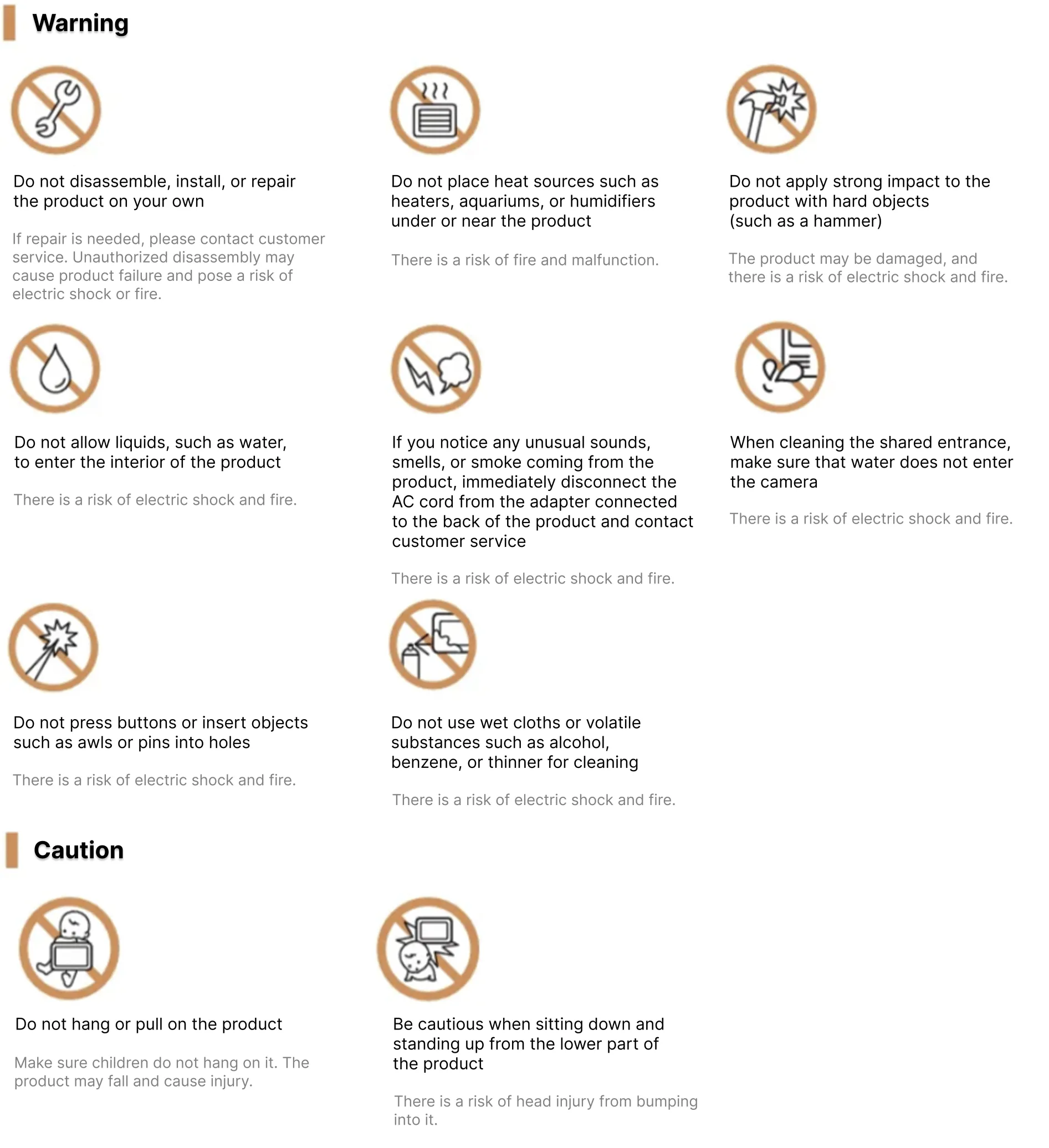
- Please pay attention to the following instructions to use the product safely and correctly.
- The sensitivity of the touch button may change at certain frequencies, but this is a normal operation.
- Failure to follow the instructions may result in serious injury or death, as well as user injury or property damage.
Product Components
Inside the box
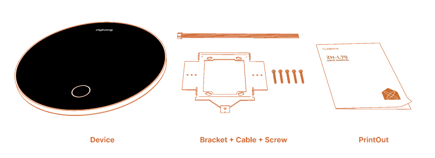 *Adaptor (ZA-HDA-11K) & Flush Mount Box (ZA-HIB-10X) are sold separately.
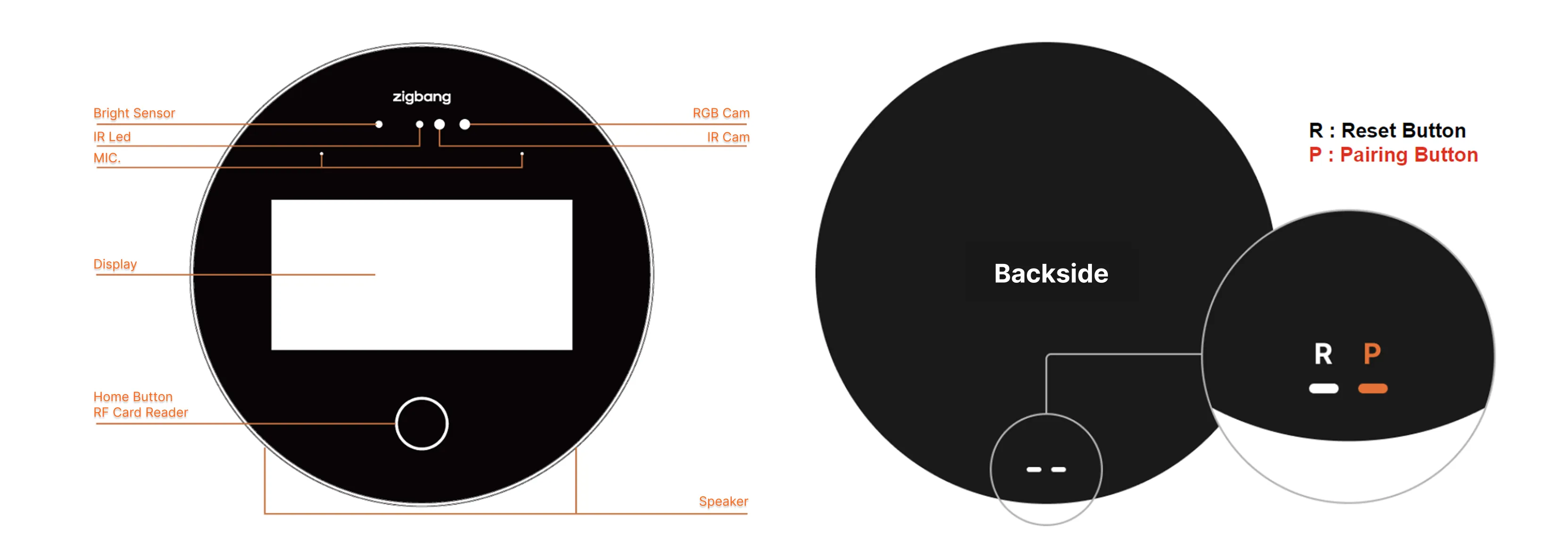
Name and Function
Specifications
Main Specifications
| Category | Specifications |
|---|---|
| OS | Android Ver.13 |
| Power | USB-C 45W or higher PD Adaptor (20VDC, 2.25A or higher) |
| Display | 6.01” OLED (2160 x 1080) |
| Camera | 2MP (RGB), 1.3MP (IR), IR LED (5.25W) *Equipped with Auto Face Detection, angle adjustment is not required. |
| Communication | Default : LAN, BLE Optional : Wi-Fi, LTE |
| Button | Front side : Home Button Back side : Reset Button & Pairing Button |
| MIC. | 2 EA |
| Speaker | 2 EA (Echo Cancellation, Noise Reduction) |
| Sensor | Brightness & Proximity |
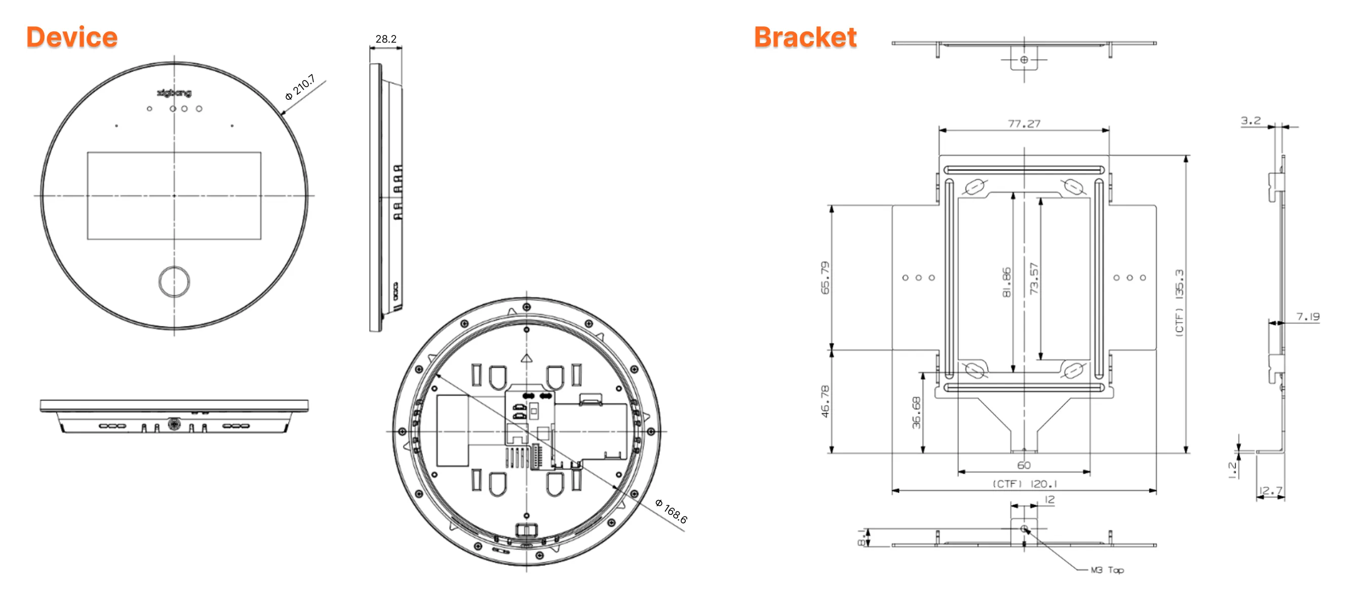
| Size | 210.7 x 28.2mm (Φ x D mm) |
| I/O | Fire Alarm Control Panel : 24VDC or 12VDC Automatic Door Contact : N/O or N/C Automatic Door Open Detection : 12VDC |
| Access Control | Face Recognition (Walk-Through, Auto Face Detection), Mobile Key Tag, RF Card, Guest Passcode *Supports a maximum of 12,000 entries per access key, based on a single local building |
| Call Method | Voice Recognition, Smart Phone (QR Scanning) Call |
| App Video Call | Supported |
| Ambient temperature | -20℃ ~ 55℃ / 90% |
| IP Rating | IP43 |
| Certification | KC |
| ETC | User App, Install App, Management Admin Voice Assistant |
Features
| Category | Features and Specifications |
|---|---|
| CPU (Speed) | 4xCortex-A53 up to 1.8 GHz Cortex-M7 up to 800 MHz |
| OS | Android Ver.13 |
| Power | 20VDC/2.25A (ZA-HDA-11K) |
| Maximum Power Consumption | Max. 45W |
| Display Monitor Screen Size | 6.01" AMOLED |
| AMOLED Resolution (Resolution : dot) | 2160(H) x 1080(W) |
| Display Screen Viewing Angle (Typ.) | the front side 45° (Z) ±15° |
| LCD Back Light Life span | 15,000 hours +25℃ |
| RGB Camera | MIPI, 2Maga pixels, CMOS, Input 1.8V |
| IR Camera | MIPI, 1.3Mage pixels, CMOS, Input 1.8V |
| SDRAM MEMORY | LPDDR4 4G |
| FLASH MEMORY | eMMC 32GB |
| Call Type | Hands-free type |
| RF Reader | 13.56MHz |
| Sensor - Distance | mmWave Distance detection sensor , 2000㎝(Max), 88°(H), 110°(E) |
| Bluetooth | Bluetooth V5.2, 2.4G |
| WIFI/BT Combo (Option) | 802.11a/b/g/n/ac/ax 1200Mbps WLAN(2.4/5G) + Bluetooth v5.2(2.4/5G) Combo M.2 Card |
| Ring Tone | Melody |
| Size | 210.7 x 28.2mm (Φ x D mm) |
| Weight (Main Body) | About 500g |
| Certification | KC |
Installation Materials Specifications
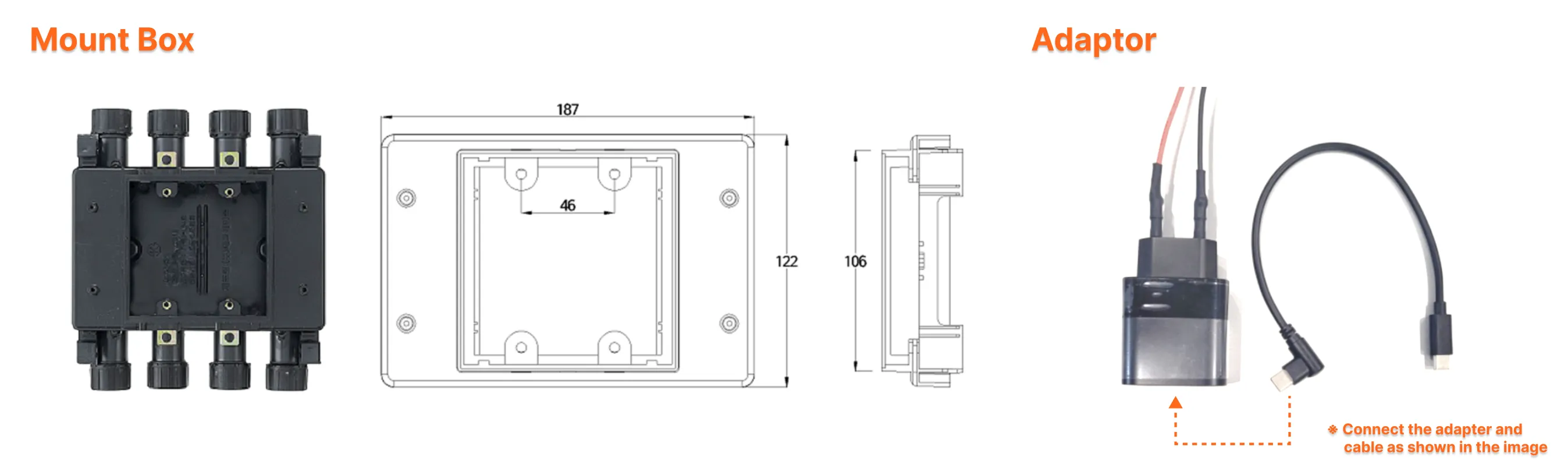
| Item | Name | Product code | Purpose | Remarks |
|---|---|---|---|---|
| Box | Flush Mount Box | ZA-HIB-10X | Box installed flush with the surface | Con cover 2-Gang (Fixing Distance 46mm) - Internal 3-Gang Type Flush Mount Box |
| Etc. | USB-C 45W PD Adapter | ZA-HDA-11K | DC20V /2.25A | USB-C 45W or Higher PD Adapter |
*Adapter (ZA-HDA-11K) & Flush Mount Box (ZA-HIB-10X) are sold separately. *Connect the adapter and cable as shown in the image. (Pay attention to the connection direction)
Wiring Specifications
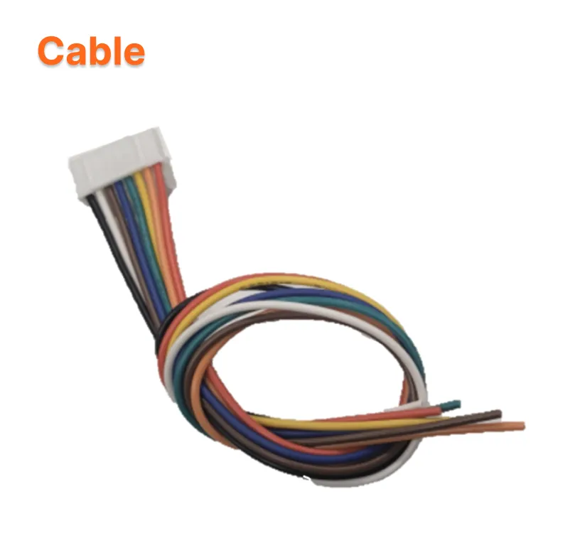
| Start Point | End Point | Comm. Method | Wiring | Distance limit (m) | Power Supply | Purpose | Terminal Processing |
|---|---|---|---|---|---|---|---|
| S/W HUB | ZH-L70-CUAK | LAN | UTP CAT5 4P (8C used) separate power supply | 100 | AC | Integrated Information Delivery | RJ45 - RJ45 |
| ZH-L70-CUAK | Automatic Door | Contact | TIV 0.8 / 4-wire (2C contact, 2C door open detection) |
30 | - | Contact | Port - Port |
| ZH-L70-CUAK | Fire Alarm Control Panel | Contact | TIV 0.8 / 2-wire | 30 | - | Contact | Port - Port |
*The contact cable is a material included in the product package.
Installation
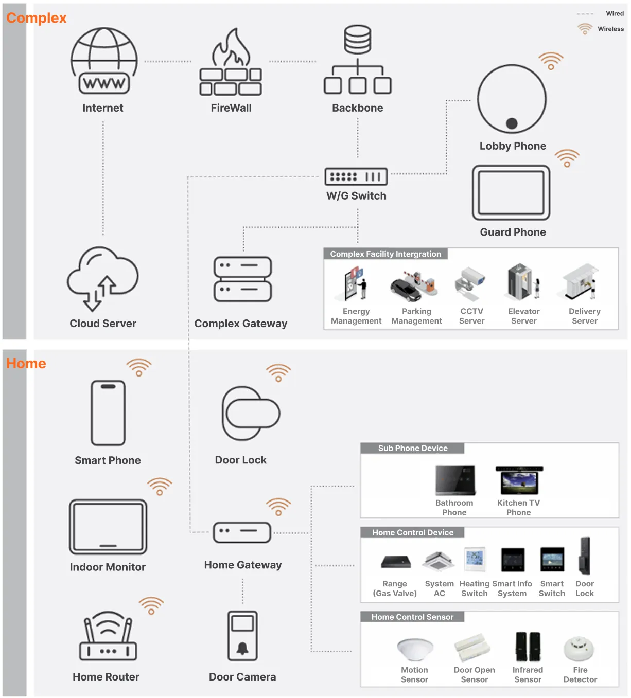
System Configuration
- This configuration diagram may vary depending on the application site.
- The system supports both wired (LAN) and wireless (Wi-Fi, LTE) connections, and can be configured in the same way as the existing home network system.
How to Install
When flush mount box is already installed
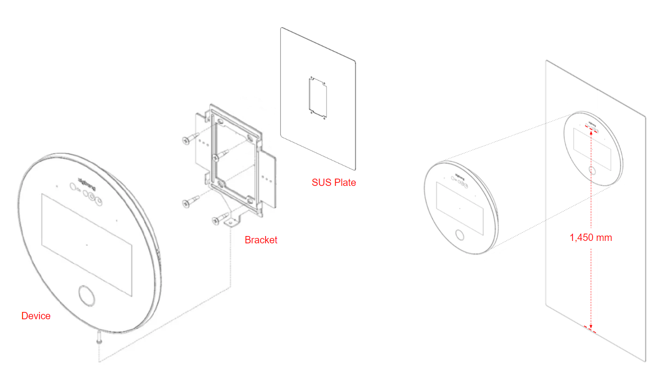
1️⃣ Check the flush mount box and the hole size around the installation area, then prepare an SUS plate (reinforcement plate) that can cover the hole. 2️⃣ Drill the SUS plate for wiring extraction, then install the SUS plate over the drilled area.
- Dark, non-glossy SUS plate is recommended. Example: Black matte SUS plate 3️⃣ Install the bracket on the SUS plate to secure it.
- It is recommended to install it at a height of 1,450 mm, based on the device camera position.
- The bracket is included in the product package. 4️⃣ Perform the wiring by referring to the installation environment of the site and the wiring diagram on the back of the product.
- Adapter (ZA-HDA-11K) is sold separately. However, depending on the site conditions, a commercially available USB-C 45W PD adapter can also be used. 5️⃣ Secure the product to the bracket.
*Equipped with Auto Face Detection, angle adjustment is not required.
When flush mount box is not installed
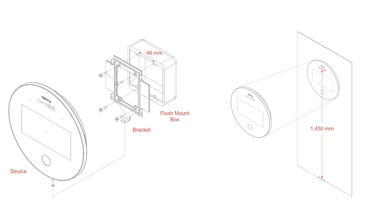
1️⃣ Drill the hole for inserting the flush mount box according to the recommended installation height.
- It is recommended to install it at a height of 1,450 mm, based on the device camera position. 2️⃣ Secure the flush mount box to the drilled area.
- Flush Mount Box (ZA-HIB-10X) is sold separately.
- Depending on the site conditions, a 2-gang Flush Mount Box (46mm screw fastening distance for the Con cover) can also be used. 3️⃣ Install the bracket onto the Flush Mount Box to secure it.
- Depending on the site conditions, an SUS plate (reinforcement plate) can be installed first, followed by the bracket.
Dark, non-glossy SUS plate is recommended.
Example: Black matte SUS plate. 4️⃣ Perform the wiring by referring to the installation environment of the site and the wiring diagram on the back of the product. - The adapter (ZA-HDA-11K) is sold separately.
However, depending on the site conditions, a commercially available USB-C 45W PD adapter can also be used. 5️⃣ Secure the product to the bracket.
*Equipped with Auto Face Detection, angle adjustment is not required.
Terminal Configuration
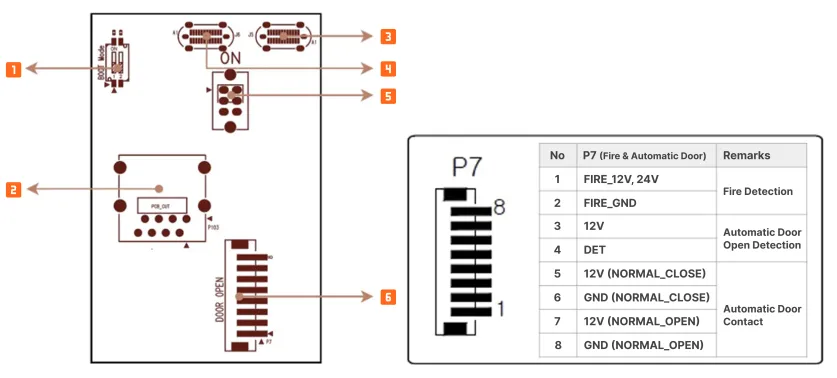
| No. | Terminal | Remarks |
|---|---|---|
| ① | Boot Mode Setting Switch (Dip-Switch) | If a manual software upgrade is required, the mode can be changed. |
| ② | LAN Port (RJ-45) | Use a cable with a specification of UTP CAT5 or higher. |
| ③ | Power (USB-C) | Connect a USB-C PD adapter with 45W or higher output. |
| ④ | Download Port (USB-C) | Used during manual software upgrade. |
| ⑤ | Power Switch (Dip-Switch) | The power can be turned On/Off. |
| ⑥ | Automatic Door Contact, Fire Detection, Automatic Door Status Check (8-pin) | Refer to the P7 connector pin map. |
Product Settings
Install App
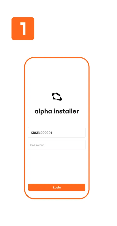
- The installation file for the Install App and the access account will be provided separately to the installer by Zigbang.
- Installation of the app via the Smart Phone Store is not supported.
- After installing the Install App, the installer will log in using the provided access account.
- The Install App is only available for use on Android OS phones.
Device Pairing
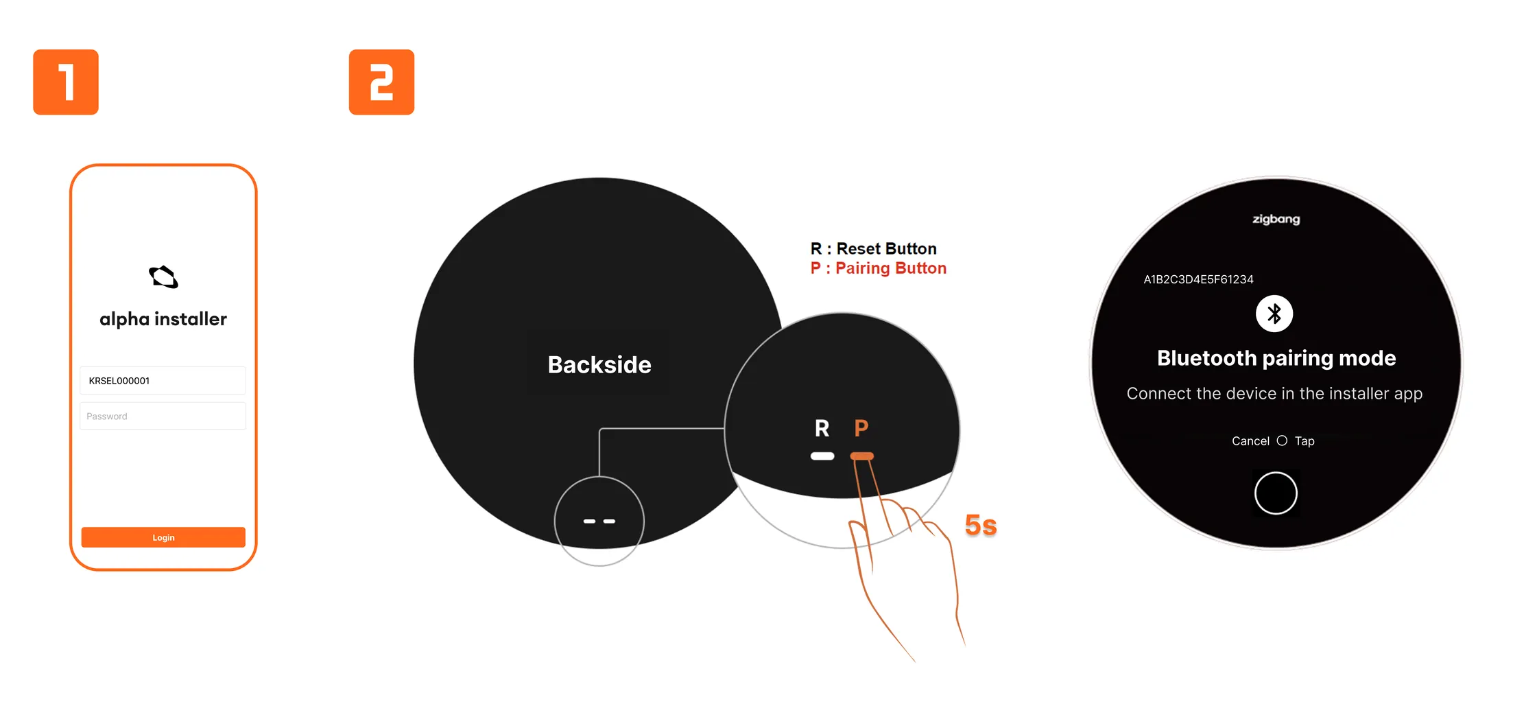
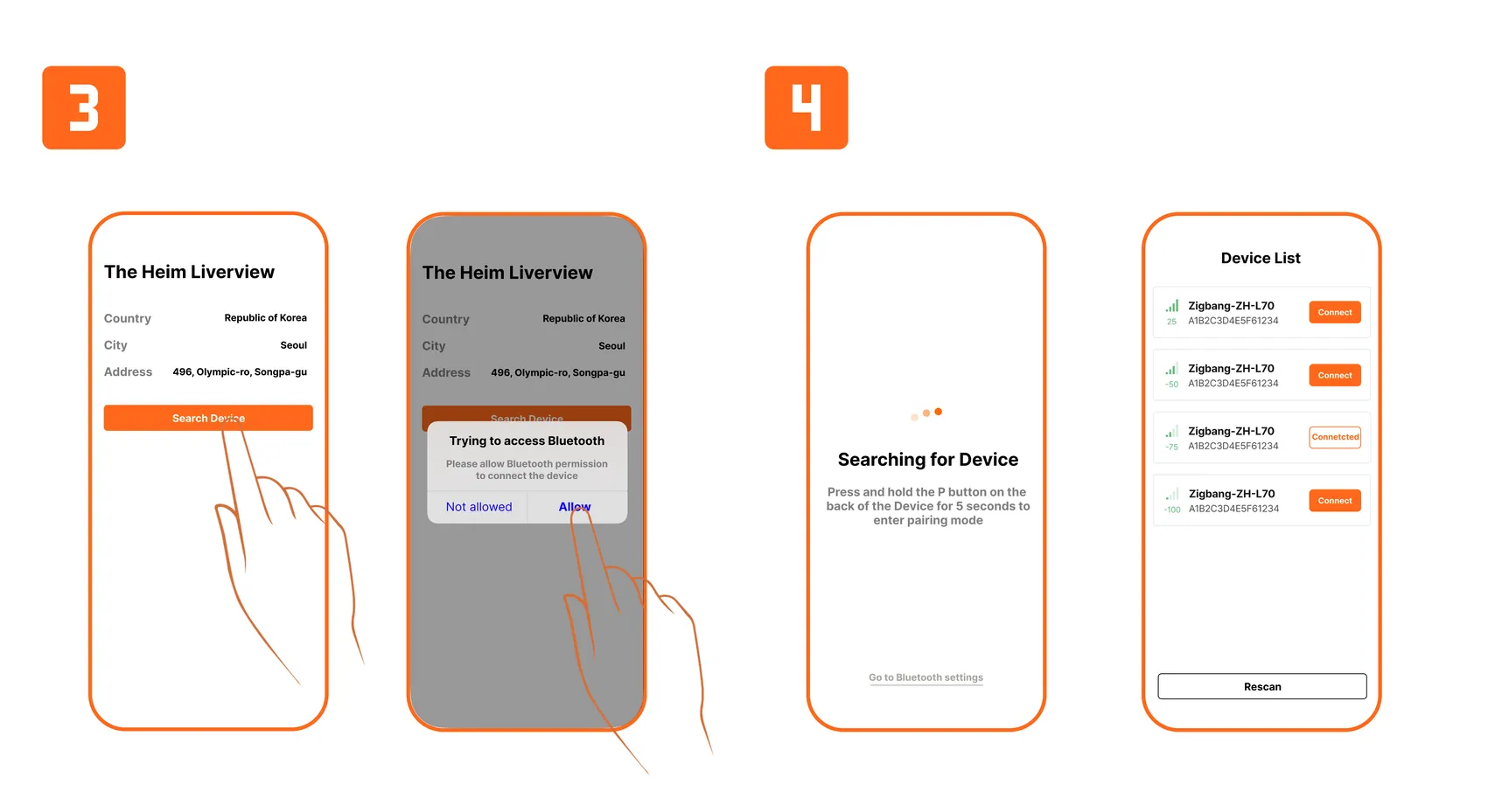
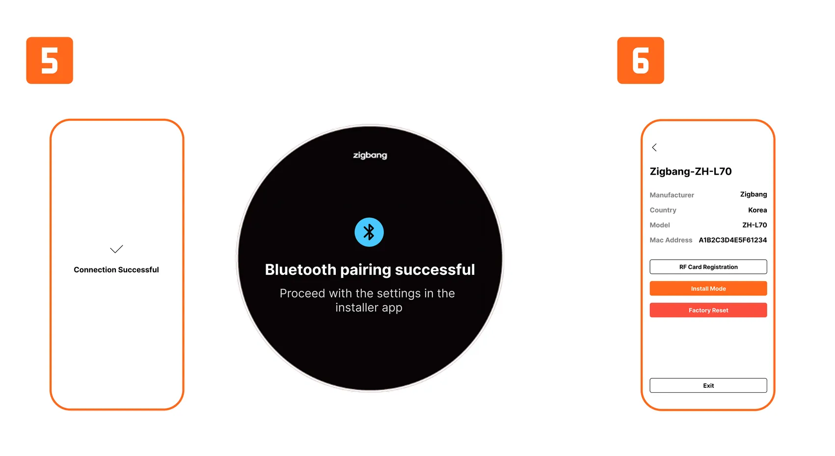
- To set up the device and register a temporary RF card, the Zigbang Install App must be installed.
- After installing the Zigbang Install App, position yourself near the device and follow the guide to complete the device pairing.
- The values entered in the guide are examples, and each value should be entered according to the site information.
- You can end the device pairing by tapping the ‘Finish’ button in the Zigbang Install App.
*To use the Install App, the Bluetooth option on your smartphone must be turned on.
Device Settings
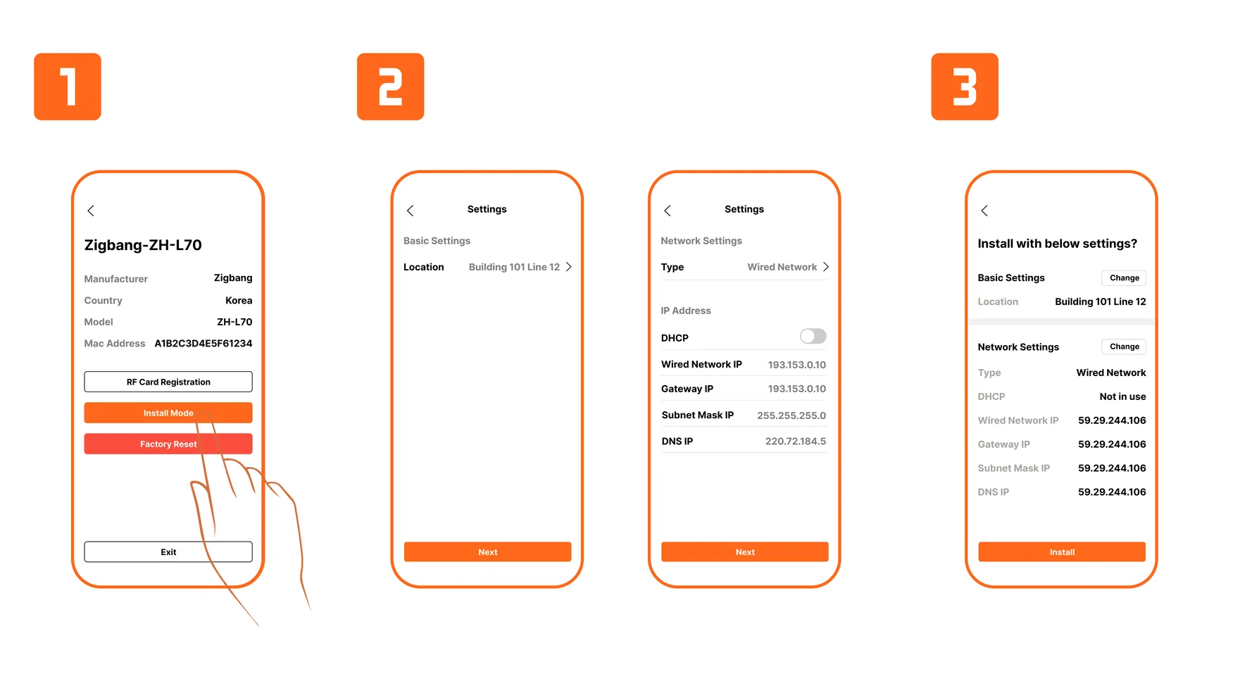
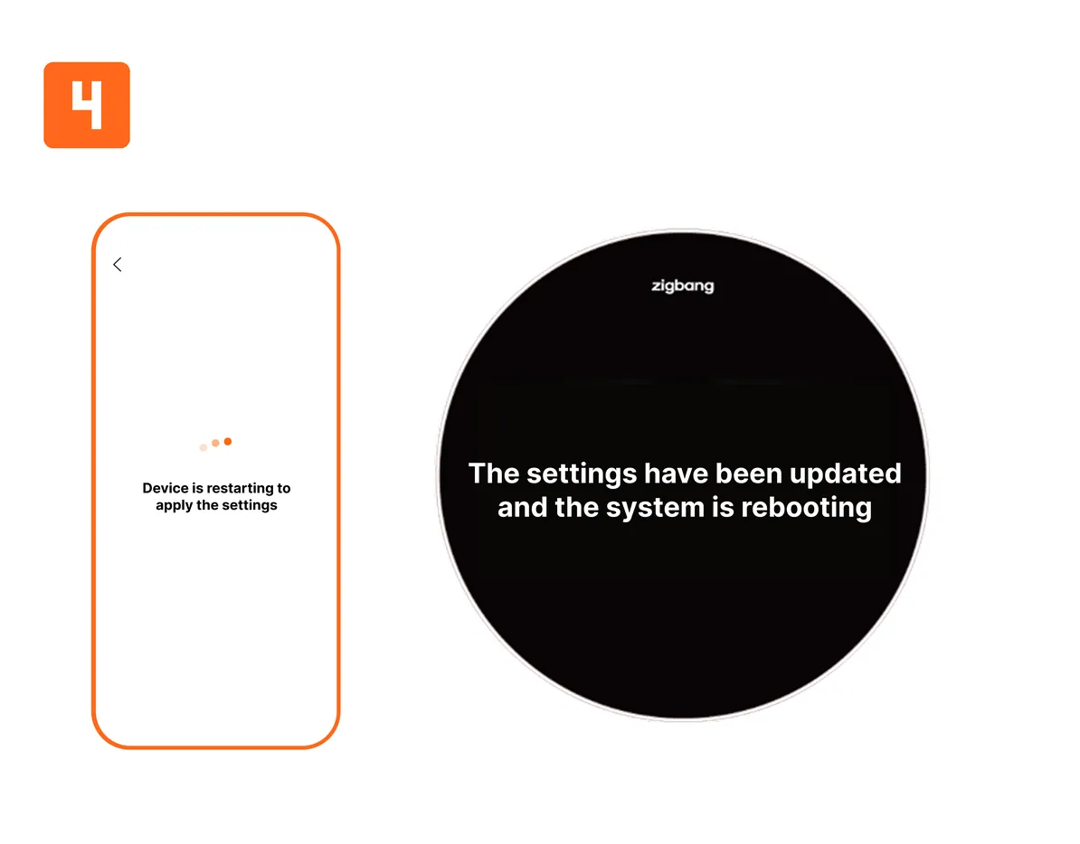
- After completing the device pairing, proceed with the device settings according to the guide.
- Tap the 'Install Mode'.
- The values entered in the guide are examples, and each value should be entered according to the site information.
Temporary RF Card Registration
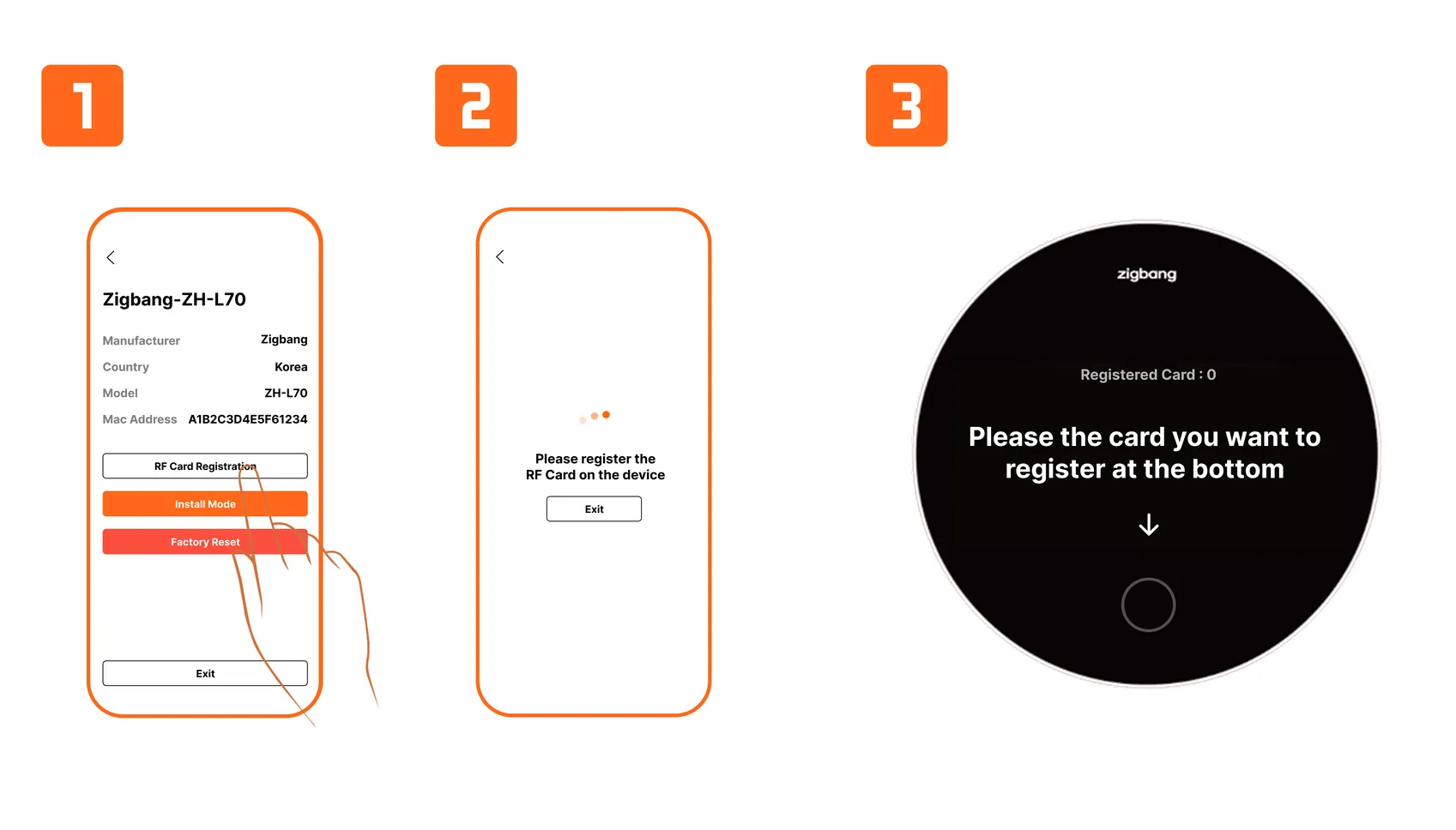
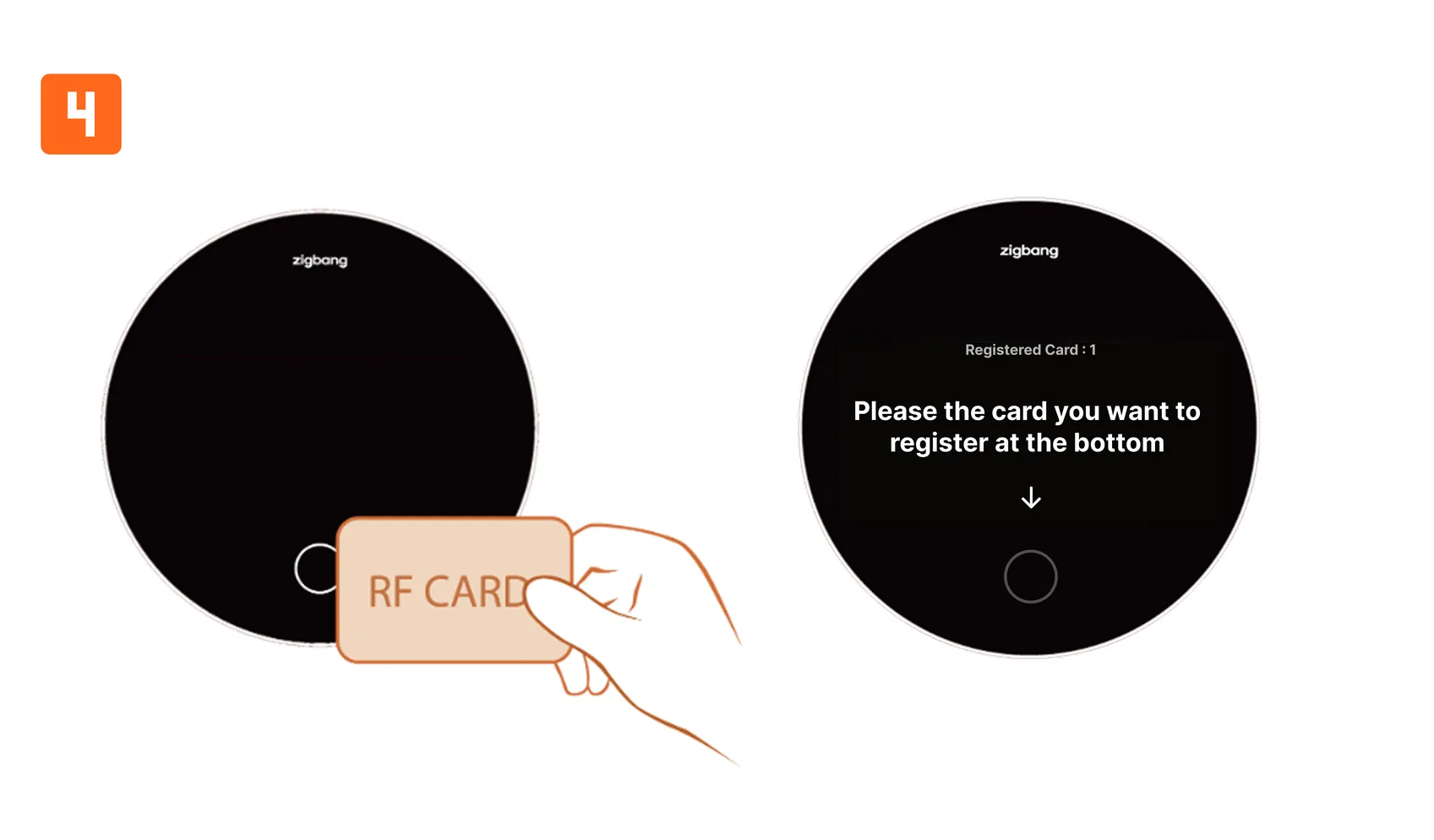
- After completing the device pairing, you can proceed with registering the temporary RF card according to the guide.
- Each time an RF card is registered, the 'Registered Card' value on the device increases, and continuous RF card registration is possible.
- You can exit the temporary RF card registration mode by tapping the 'Exit' button in the Zigbang Install App.
*This is the RF card registration feature for temporary access when the device is not initially connected to the cloud server. *Once the public area internet installation and cloud server integration are completed at the site, all registered temporary RF card information will be deleted. *After the cloud server integration, RF card registration can only be done at the management office.
Device Factory Reset
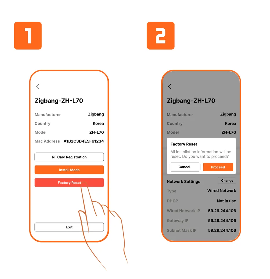
- After completing the device pairing, you can proceed with the factory reset according to the guide.
- When the ‘Reset’ button is pressed, the device will be restored to its factory default settings.
Additionally, by simultaneously pressing the Home Button on the front of the device and the Pairing Button on the back, the device will enter Factory Reset.
*Please note that during the factory reset, all information registered on the device will be deleted.
Trouble Shooting
- When a malfunction occurs, follow the guide below to take appropriate action.
Symptom Countermeasure When the power is On but the LED does not light up. 1. Check the adapter
2. Check the adapter’s cable connection
3. Ensure that the adapter’s power is 20V (±10%).If the UI is not displayed on the OLED 1. Check the power status and oscillation of the Main Board PMIC.
2. Check the output terminal of the Base Board OLED power IC.
3. Verify the FPC connection between the Base Board and the OLED panel.
4. Check the status of the Base Board.
5. Check for any issues with the OLED panel.If the rear Reset Key and Pairing Key are not functioning 1. Check the connection between the Key Board and the Base Board.
2. Check the button status and assembly of the Key Board.
3. Verify that the voltage at pins 1 and 3 of Base Board P404 is outputting 1.8V.If the Home Button is not functioning properly 1. Check the assembly of the Touch Board.
2. Verify that the voltage at pin 2 of Base Board P401 is outputting 3.3V.If the Ethernet connection is not working 1. Check the cable connection of Base Board P103.
2. Verify the oscillation state of Base Board Y3 (25MHz).
3. Check the lighting of LED2 and LED3, as well as the EtherNet IC (U27) and surrounding circuits.If the melody and speaker are not functioning properly 1. Check the connection of the Base Board Speaker (P23, P24).
2. Verify the status of the Base Board Audio IC (U81).
3. Check the status of the Speaker AMP (U42, U46).If the call function is not working properly 1. Check the connection between the Main Board and Base Board.
2. Verify the settings (Building/Unit number) information.
3. Check the LAN cable and communication status.If there is no transmission or reception during a call 1. Check the connection of the Speaker and MIC.
2. Verify the gain input status.
3. Check the status of the Base Board Audio IC (U81).If the video output on the OLED is not functioning properly during facial recognition 1. Check the connection of the Camera Module (P1009, P1010).
2. Verify that the power ICs (U48, U52, U51, U50, U49, U47) are outputting correctly.If the video output of the device is not functioning properly during a call 1. Check the communication environment and communication speed.
2. Verify the connection of the Camera Module (P1010).If the Mobile Key Tag is not functioning properly 1. Check the antenna connection of the Bluetooth Module J5.
2. Verify the assembly status of the M2-type Module on Base Board J1101.If the Welcome LED is not functioning properly 1. Check the connector connection of Base Board P403.
2. Verify that the voltage at pin 1 of Base Board P403 is outputting 3.3V.
3. Check the status of the Welcome LED Board.
Product Disassembly
Disassembly & Assembly
- Instructions
⚠️ ESD (Electrostatic Sensitive Devices) Caution
When handling boards or components, be cautious to prevent product damage caused by static electricity.
Therefore, always wear a wrist strap before handling boards or components.
1️⃣ Remove 12 screws, then gently pull apart the back section to separate the product.
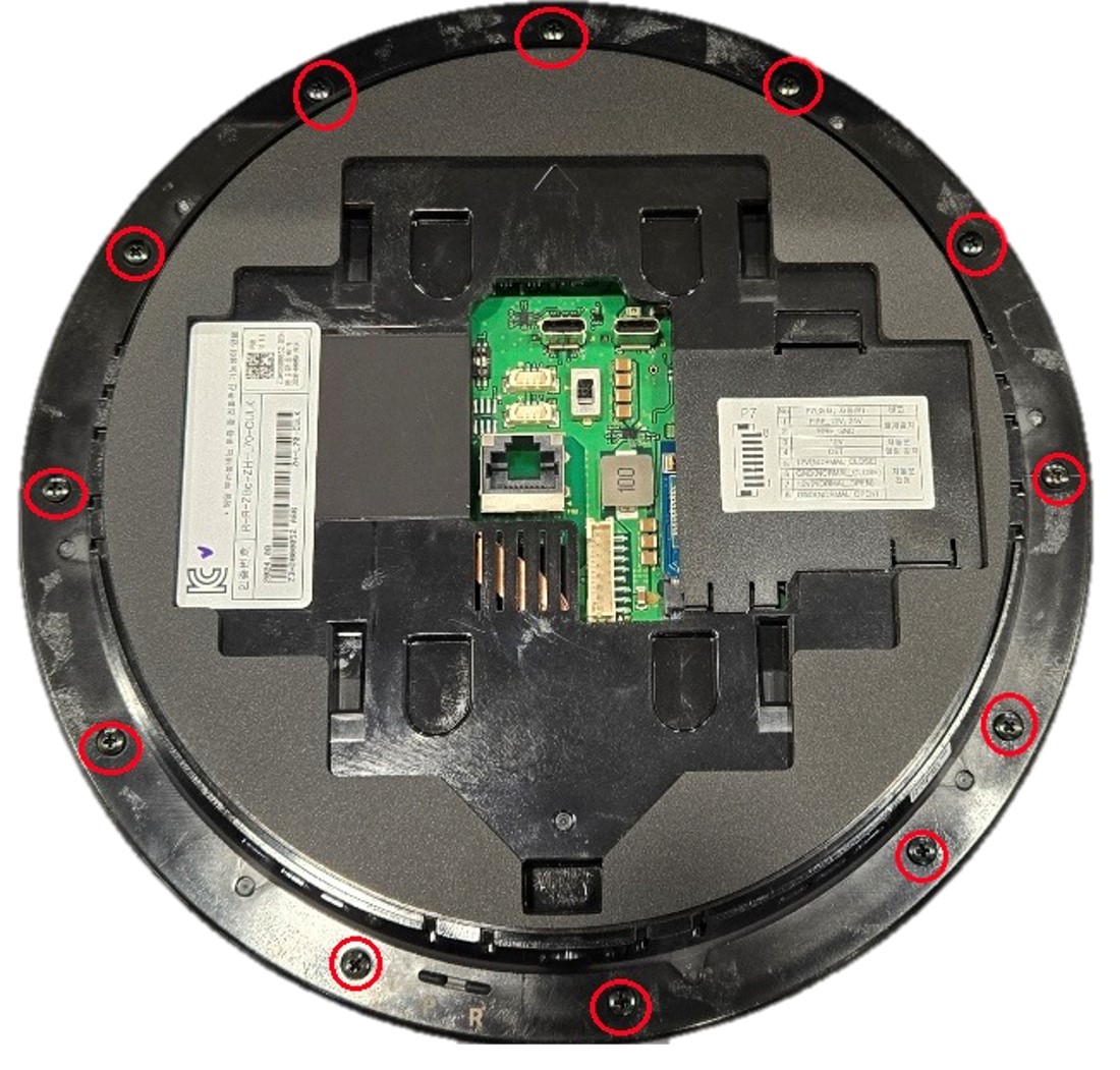
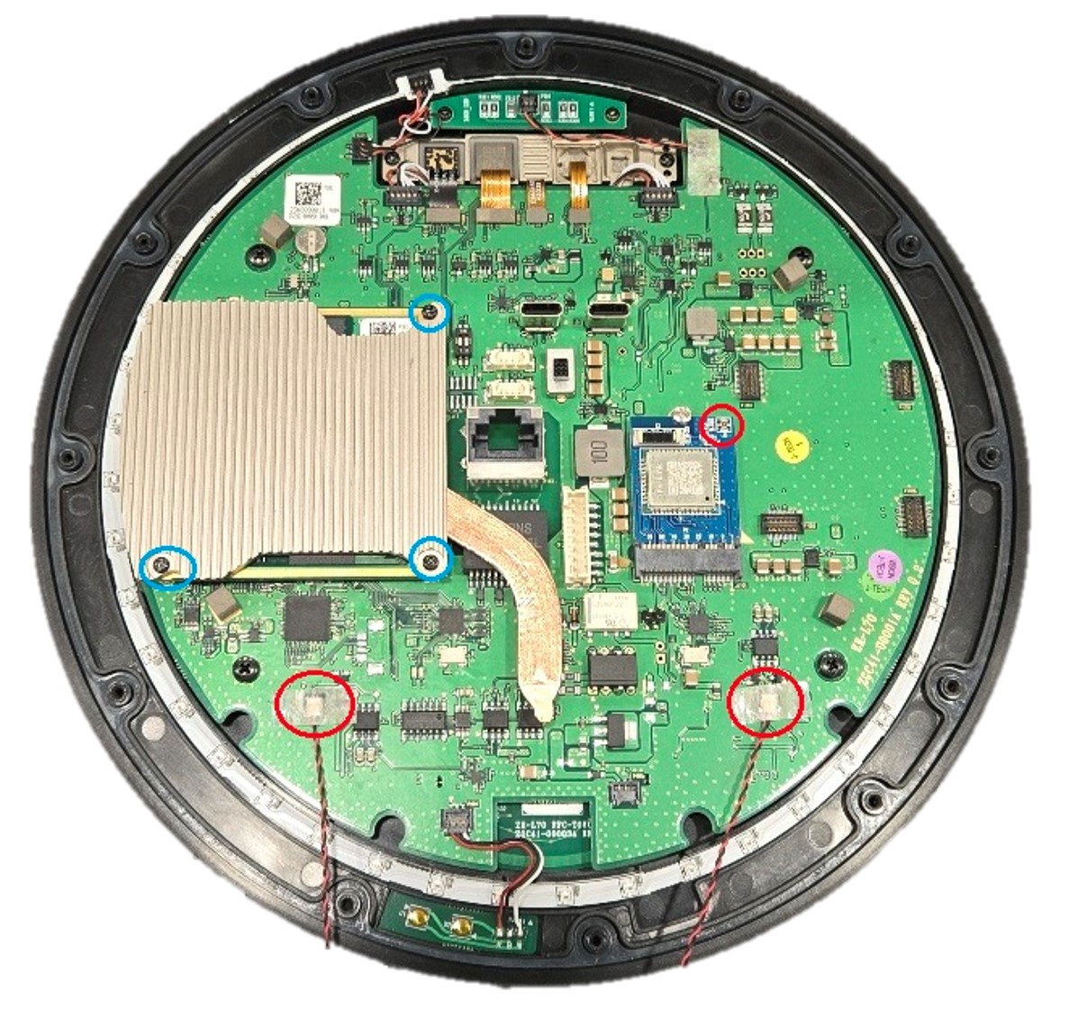
2️⃣ After removing the bottom case, disconnect the cables from the two speakers and the BT ANT connector. Then, remove the three screws (3 EA) from the HEAT-SINK PIPE ASSY.
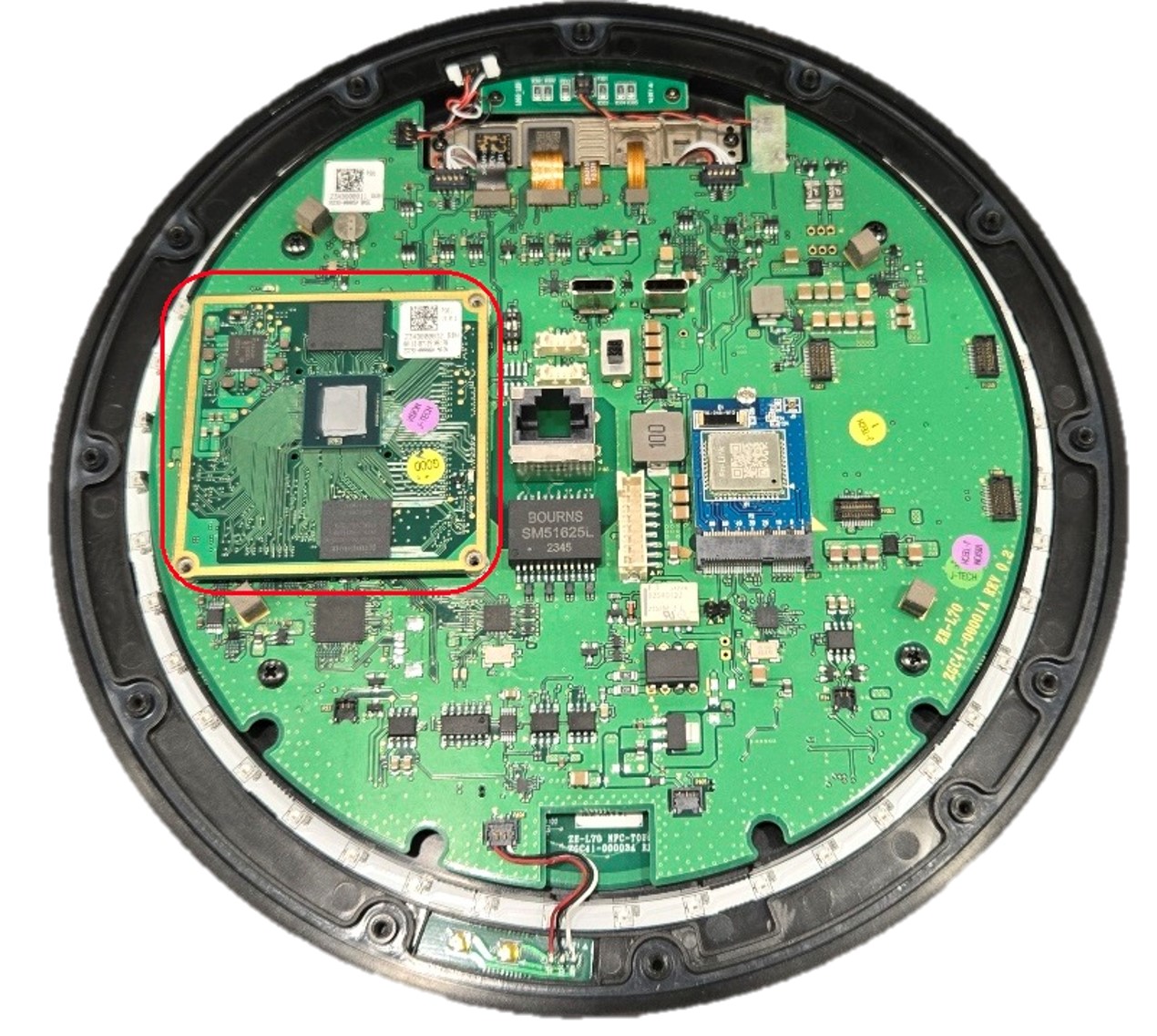
3️⃣ Separate the Main Board from the Base Board.
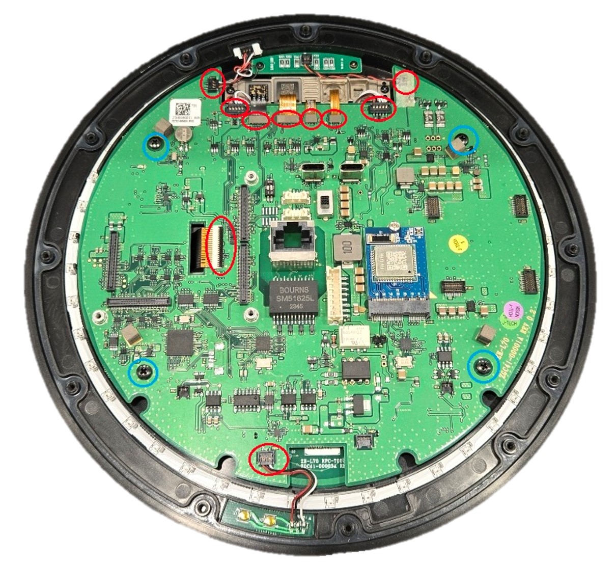
4️⃣ Disconnect the Deco LED, Logo LED, two microphones, Camera ASSY, OLED, and Reset S/W. Then, lift the Base Board from the bottom to the top to remove it.
5️⃣ Remove the screws from the NFC Touch PBA, Logo LED, Camera ASSY, and OLED bracket.
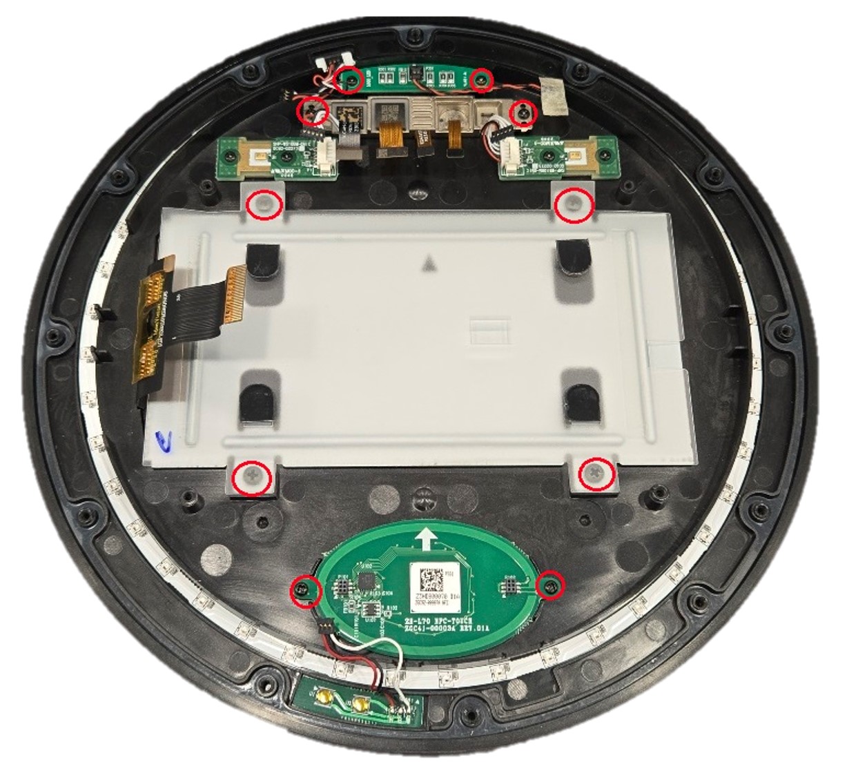
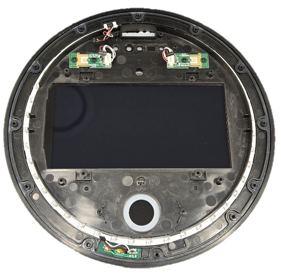
6️⃣ The MIC, Deco LED, and Reset PBA are attached to the Top Case with adhesive tape and cannot be removed.
7️⃣ Assembly is carried out in the reverse order of disassembly.
- Detailed exploded view
Components
| Component | Name | Product Code |
|---|---|---|
| Display | OLED Module | ZGC07-00001A |
| PBA | Main PBA | ZGC92-00006A |
| Base PBA | ZGC92-00005A | |
| NFC-Touch PBA | ZGC92-00007A | |
| Reset PBA | ZGC92-00009A | |
| Logo LED PBA | ZGC92-00008A | |
| MIC. PBA | ZGC92-00010A | |
| MIC. PBA | ZGC92-00011A | |
| Camera | ELA Module - Camera | ZGC96-00001A |
| Speaker | ELA Module | ZGC96-00002A |
| Harness | Circle LED Wire | ZGC39-00003A |
| Logo LED Wire | ZGC39-00002A | |
| Reset Wire | ZGC39-00004A | |
| MIC. Wire | ZGC39-00001A | |
| Install Wire | GC39-00463A | |
| Hardware | Window | ZGC63-00003A |
| Case - Top | ZGC61-00002A | |
| Case - Bottom | ZGC61-00054A | |
| SINK PIPE ASSY | ZGC96-00007A | |
| Bracket - OLED | ZGC61-00005A | |
| Bracket - Wall | ZGC61-00055A |
THE END